
Time to step outside of the realm of dyno charts, peak horsepower numbers, peak torque number and all those other numbers that people like to brag about and step into the realm of reality where we can see how these numbers actually effect real world performance. The engine is only a third of the drive train that makes the difference between fast and slow. one of the others is tires, which we won't discuss here and the other is the transmission. The transmission is what takes the power your engine produces, and transforms it into usable power by the wheels. During this transformation it amplifies it using a set of gears and a final drive.
Cars apply gearing in two different ways. The first is in the transmission where we have 5 different gears that are changed to accommodate a wide range of vehicle speed. The second is the differential which provides additional mechanical advantage to the wheels. Now these two parts can either be connected by a drive shaft (as they are in rear wheel drive cars) or they can be combined into what is called a trans-axle (as they are in front wheel drive cars like our Tegs) Forgive me if you know this already but I want to cover the basics so everyone is on the same page.
Here are the gear ratios and final drive for the USDM Type R
![Image]()
Gear Ratios for all other Integras including the RSX can be found here
In first gear, the engine will make 3.23 revolutions for every one revolution of the transmission's output. In 5th gear, it will only make 0.848 revolutions for every 1 revolution of the transmission's output. 5th gear is actually an overdrive gear because the transmission's output is rotating faster than the engine.
The Type R's final drive ratio is 4.4 This means that for every 4.4 revolutions of the transmission's output, the wheels turn once. The transmission ratio multiplies with the differential ratio so in 1st gear, the engine will spin 14.212 times for every time the wheel spins once. All you are basically doing here is multiplying the ratio for gear one by the ratio of the final drive (4.4 * 3.23 = 14.212)
Here is a chart with all the USDM G3 transmission gear ratios and final drives.
![Image]()
Looking at this chart we can see that as you move from right to left (from the ITR to the LS AUTO) the speed of the engine per one wheel rotation gets smaller as you go. This is why an Integra with an ITR transmission has to rev higher to go 60 mph than it would had it had an LS or GSR transmission.
Now that we understand what gear ratios are and how they work, lets move on to thrust. Thrust is very simple. It is the force that your tires exert on the road surface. In accordance with Newton's Third Law, for every action there is a equal but opposite reaction, the road produces an equal reaction on the tires and thus the car is propelled forward. To put this more simply, thrust is what makes the car accelerate. You can feel it every time you hit the gas as you get sucked back in to the seat.
Ok so now we know what all three things are, so how do they relate?
The answer comes in the form of a simple equation. Thrust = Torque * Gear Ratio * Final Drive.
Torque is the raw power that comes from the engine. Your gear ratio and final drive are merely mechanical devices that amplify the power coming from your engine. Lets face it, if you merely had the engine connected directly to the drive shaft, the car would not accelerate very fast at all. But, if you multply that torque 14.212 times (as the Type R transmission does in 1st gear) well, now we are talking.
So, as we can see, torque and thrust are directly related since torque is the only variable within any given gear (unless we are talking about a continuously variable transmission which is waaaaaaaaaaaaay outside of the scope of this thread and its also not commercially available for the Integra anyway) So if torque is the only variable, if we were to plot a thrust chart, the line would look EXACTLY like our torque curve.
The advantage of using thrust as opposed to a dyno plot of torque is that it shows the real difference in power between all 5 gears. A dyno only shows you oNE GEAR and it is almost always the gear that is closest to a 1:1 ratio.
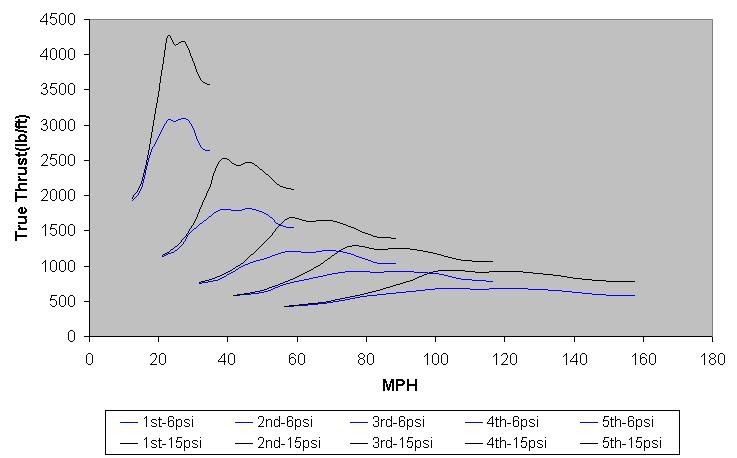
Here is an example of a thrust chart of a GSR usning a GSR transmission with the rev limit set to 8800 RPMs. Credit for the chart goes to Michael Delaney.
![Image]()
Here you can see the power differences between the gears. Heres where this becomes useful. The line at the top is first gear. Where that line ends is where the driver will shift to 2nd gear. If you drop straight down from the end of the 1st gear line to the 2nd gear line you will notice it lands him right at the beginning of the engine's power band. This happens again from 2nd to 3rd. From 3rd to 4th as well as from 4th to 5th you can see its smack in the middle.
What does this graph show us? It shows us that this engine and transmission are working perfectly together, allowing the engine to land in its peak operating RPM range after each shift. When this happens, you get the fastest possible acceleration that engine can provide. It also shows us that there is absolutely no benefit to shifting before redline. Even though the power is starting to drop off late in the range, you are still making more thrust than you would in the higher gear at that wheel speed. To illistrate this point more clearly, at 80 kph, the car will produce about 500 foot pounds of wheel torque in 4th gear. But in 3rd gear at the SAME speed it produces about 700 foot pounds. Which gear would you rather be in?
There are 2 ways we can work with this. You can either use this to select a transmission that works with your engine's power band OR you can use this to help with tuning the car and placing your power band where your transmission can make the most of it. Either was is acceptable because the end result will be the same.
I delved into this topic back on 08 and never really finished because of a lack of funds. I wanted to build a frankenstein transmission and ploted several thrust charts with different combonations to see what would work best with my setup. If you want to see those charts and the brief explaination that followed, click here.
Here are some other threads that may help explain anything that is unclear.
Thrust Curves
What is a powerband?
Torque is what makes you accelerate
Gear Ratios Final Drives and Torque
Questions, comments, want to discuss/(maturely)debate something don't hesitate. Don't foget this forum is for serious discussion only and all posts must be approved by a moderator regaurdless of how long you have been a member.
Cars apply gearing in two different ways. The first is in the transmission where we have 5 different gears that are changed to accommodate a wide range of vehicle speed. The second is the differential which provides additional mechanical advantage to the wheels. Now these two parts can either be connected by a drive shaft (as they are in rear wheel drive cars) or they can be combined into what is called a trans-axle (as they are in front wheel drive cars like our Tegs) Forgive me if you know this already but I want to cover the basics so everyone is on the same page.
Here are the gear ratios and final drive for the USDM Type R

Gear Ratios for all other Integras including the RSX can be found here
In first gear, the engine will make 3.23 revolutions for every one revolution of the transmission's output. In 5th gear, it will only make 0.848 revolutions for every 1 revolution of the transmission's output. 5th gear is actually an overdrive gear because the transmission's output is rotating faster than the engine.
The Type R's final drive ratio is 4.4 This means that for every 4.4 revolutions of the transmission's output, the wheels turn once. The transmission ratio multiplies with the differential ratio so in 1st gear, the engine will spin 14.212 times for every time the wheel spins once. All you are basically doing here is multiplying the ratio for gear one by the ratio of the final drive (4.4 * 3.23 = 14.212)
Here is a chart with all the USDM G3 transmission gear ratios and final drives.

Looking at this chart we can see that as you move from right to left (from the ITR to the LS AUTO) the speed of the engine per one wheel rotation gets smaller as you go. This is why an Integra with an ITR transmission has to rev higher to go 60 mph than it would had it had an LS or GSR transmission.
Now that we understand what gear ratios are and how they work, lets move on to thrust. Thrust is very simple. It is the force that your tires exert on the road surface. In accordance with Newton's Third Law, for every action there is a equal but opposite reaction, the road produces an equal reaction on the tires and thus the car is propelled forward. To put this more simply, thrust is what makes the car accelerate. You can feel it every time you hit the gas as you get sucked back in to the seat.
Ok so now we know what all three things are, so how do they relate?
The answer comes in the form of a simple equation. Thrust = Torque * Gear Ratio * Final Drive.
Torque is the raw power that comes from the engine. Your gear ratio and final drive are merely mechanical devices that amplify the power coming from your engine. Lets face it, if you merely had the engine connected directly to the drive shaft, the car would not accelerate very fast at all. But, if you multply that torque 14.212 times (as the Type R transmission does in 1st gear) well, now we are talking.
So, as we can see, torque and thrust are directly related since torque is the only variable within any given gear (unless we are talking about a continuously variable transmission which is waaaaaaaaaaaaay outside of the scope of this thread and its also not commercially available for the Integra anyway) So if torque is the only variable, if we were to plot a thrust chart, the line would look EXACTLY like our torque curve.
The advantage of using thrust as opposed to a dyno plot of torque is that it shows the real difference in power between all 5 gears. A dyno only shows you oNE GEAR and it is almost always the gear that is closest to a 1:1 ratio.
Here is an example of a thrust chart of a GSR usning a GSR transmission with the rev limit set to 8800 RPMs. Credit for the chart goes to Michael Delaney.

Here you can see the power differences between the gears. Heres where this becomes useful. The line at the top is first gear. Where that line ends is where the driver will shift to 2nd gear. If you drop straight down from the end of the 1st gear line to the 2nd gear line you will notice it lands him right at the beginning of the engine's power band. This happens again from 2nd to 3rd. From 3rd to 4th as well as from 4th to 5th you can see its smack in the middle.
What does this graph show us? It shows us that this engine and transmission are working perfectly together, allowing the engine to land in its peak operating RPM range after each shift. When this happens, you get the fastest possible acceleration that engine can provide. It also shows us that there is absolutely no benefit to shifting before redline. Even though the power is starting to drop off late in the range, you are still making more thrust than you would in the higher gear at that wheel speed. To illistrate this point more clearly, at 80 kph, the car will produce about 500 foot pounds of wheel torque in 4th gear. But in 3rd gear at the SAME speed it produces about 700 foot pounds. Which gear would you rather be in?
There are 2 ways we can work with this. You can either use this to select a transmission that works with your engine's power band OR you can use this to help with tuning the car and placing your power band where your transmission can make the most of it. Either was is acceptable because the end result will be the same.
I delved into this topic back on 08 and never really finished because of a lack of funds. I wanted to build a frankenstein transmission and ploted several thrust charts with different combonations to see what would work best with my setup. If you want to see those charts and the brief explaination that followed, click here.
Here are some other threads that may help explain anything that is unclear.
Thrust Curves
What is a powerband?
Torque is what makes you accelerate
Gear Ratios Final Drives and Torque
Questions, comments, want to discuss/(maturely)debate something don't hesitate. Don't foget this forum is for serious discussion only and all posts must be approved by a moderator regaurdless of how long you have been a member.